Fm Transmitter Diagram 10km

Hey there, tech enthusiast! Ever dreamt of broadcasting your own radio station? Yeah, I know, sounds like something out of a movie, right? But guess what? It's totally achievable, and we're gonna chat about how you can (theoretically!) create an FM transmitter with a 10km range. Now, before you picture yourself as the next Howard Stern, a big disclaimer: broadcasting without the proper license is a no-no in most places. Think hefty fines and confiscation of your cool homemade gear. So, this is purely for educational and experimental purposes, okay? Good.
The Mythical 10km FM Transmitter Diagram: What's the Hype?
Okay, so you've probably been Googling "FM transmitter diagram 10km" and have been bombarded with schematics that look like they were drawn by a spider on caffeine. Don't panic! While a true 10km range requires a bit more oomph than your average garage project can safely and legally provide, understanding the basic building blocks is still super cool. We're talking about learning the fundamentals of radio frequency (RF) electronics, which is way cooler than binge-watching cat videos (though I admit, those are pretty great).
Think of an FM transmitter like a tiny voice amplifier for radio waves. It takes a weak audio signal (maybe your favorite song, or your amazing podcast) and boosts it, then sends it out on a specific frequency for your radio to pick up. The diagram shows you how to assemble the components that make this happen.
Must Read
Key Ingredients for Our Radio Magic Potion
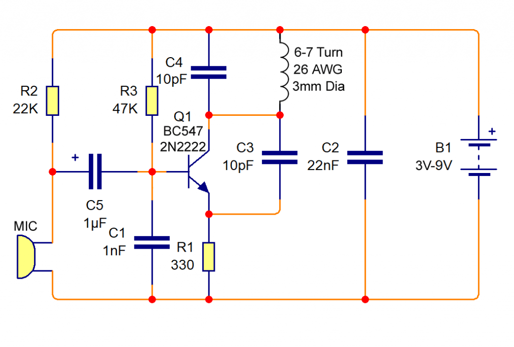
So, what's in this magical 10km-ish FM transmitter recipe? (Remember, "ish" is the operative word here!) You'll generally find these core components in any decent diagram:
- Oscillator: This is the heart of the transmitter. It generates the carrier frequency - the specific radio station number, if you will. Think of it as the beat that your radio station dances to. Common oscillators use transistors or specialized ICs.
- Modulator: This is where your audio signal gets mixed with the carrier frequency. It's like adding flavor to the base. The audio signal subtly changes (modulates) the carrier frequency, which is how the radio receives and decodes the sound.
- Amplifier: This boosts the modulated signal so it can travel further. More power equals (potentially) more range. This is where things get a little trickier, because more power also means more responsibility (and potentially needing that pesky license).
- Antenna: This is what radiates the signal into the air. The antenna's design and placement drastically affect the range and efficiency of your transmitter. A coat hanger probably won't cut it for 10km (sorry!).
- Power Supply: Gotta power the whole shebang, right? A stable and clean power supply is crucial for consistent performance.
These components are connected by circuits consisting of resistors, capacitors, and inductors, and their arrangement and values are important for a stable, strong signal.

Decoding the Diagram (Without Losing Your Sanity)
Okay, so you've found a diagram online. Now what? First, make sure it looks legitimate. A blurry picture drawn on a napkin probably isn't the best starting point. Look for clear, well-labeled diagrams with component values clearly specified. If you're new to electronics, start with a simpler diagram. There are plenty of online resources that break down each section and explain what's happening. Don't be afraid to ask for help in online forums or communities! Seriously, people love showing off their knowledge (and judging your soldering skills...just kidding...mostly).
Important Note: Working with electronics involves electricity, and electricity can be dangerous! If you're not comfortable working with electronics, please seek guidance from someone who is experienced.
Range Reality Check: Why 10km Is a Stretch
Let's be honest, achieving a consistent 10km range with a DIY FM transmitter is tough, especially without violating broadcasting regulations. Factors like terrain, antenna height, and surrounding buildings can significantly reduce the range. Also, the amplifier stage needs careful design and shielding to prevent unwanted interference and ensure signal quality. Think of it like this: you might be able to see 10km on a clear day, but radio waves face a lot more obstacles.
Think of it like trying to shout across a football field versus shouting across a crowded stadium! One is a lot easier. A 10km range requires a well-designed system, and a license to operate!

The Joy of Experimentation (Responsibly!)
Even if you don't reach the mythical 10km mark, building and experimenting with FM transmitters is an amazing way to learn about electronics and radio technology. You can create a low-power transmitter for your home or garden (within legal limits, of course!), or use it as a learning tool to understand how radio waves work. Think of it as a fun, hands-on science project that can unlock a whole new world of possibilities.
So, even if you don't become the next big radio star, you'll gain valuable skills and knowledge. And who knows, maybe one day you'll invent the next groundbreaking communication technology! The journey, not the destination, right?
Remember: Always operate within legal limits and prioritize safety. Happy tinkering!
