Ever tried putting together IKEA furniture? You know that sinking feeling when you realize you're missing a crucial screw? Suddenly, your dreams of a minimalist Scandinavian haven turn into a frantic search through the spare parts bin (or worse, a trip back to the store). That tiny screw, that seemingly insignificant piece, is the unsung hero holding everything together. Today, we're going to become screw-making heroes ourselves, but virtually! We'll craft our very own screw in SolidWorks. No more panicking over missing parts, just pure digital creation!
Getting Started: The Humble Circle
First, fire up SolidWorks. Don't worry if it looks like the cockpit of a spaceship. We'll start simple. Imagine you're drawing a circle on paper. That's basically what we're doing here. Choose a plane (front, top, right – doesn't really matter for now). Select the "Circle" tool, slap a circle down, and give it a dimension. Let's say, a diameter of, oh, 6mm. Why 6mm? Because why not! Feel free to adjust based on the size of screw you want. This circle is the foundation of our screw, the base of its magnificent thread.
Extrude Boss/Base: Making it 3D (Without the Headache)
Now for the fun part! We're going to take that flat circle and magically pull it into the third dimension. Use the "Extrude Boss/Base" feature. Think of it like squeezing Play-Doh through a shape-sorter. The circle goes in, and a cylindrical shape comes out. The length of this cylinder will determine the length of our screw. Maybe make it 30mm long? Again, totally up to you. Just don't go overboard – we're making a screw, not a space elevator.
Click OK. Boom! You've got a cylinder. Congratulations, you've essentially created a digital metal rod. But it's not a screw yet. It's just... potential.
The Helix and Spiral: Twisting Our Way to Success
This is where things get a little… *twisty*. We need to add the characteristic screw thread. SolidWorks, being the awesome software it is, has a tool for that: the "Helix and Spiral" feature. It's hidden under the "Curves" dropdown, so go hunting for it. This part often trips people up the first time, so don't fret if it takes a few tries.
Select a circular edge on your cylinder to define the base of the helix. You'll see a preview of a spiral-y thing wrapping around your cylinder. This is the thread! We need to tell SolidWorks how tight or loose to make the spiral, which is defined by the "pitch" and "revolution". Think of pitch as the distance between each thread coil. A smaller pitch means tighter threads.
Experiment with values. A pitch of 1mm and a number of revolutions that cover the length of your cylinder (around 30 revolutions in this case) is a good starting point. You might have to tweak these values to get the perfect spiral that suits your screw size. Don't be afraid to experiment! It's digital, you can't break anything (except maybe your own patience, but we'll get through this together).
Swept Cut: Carving the Thread
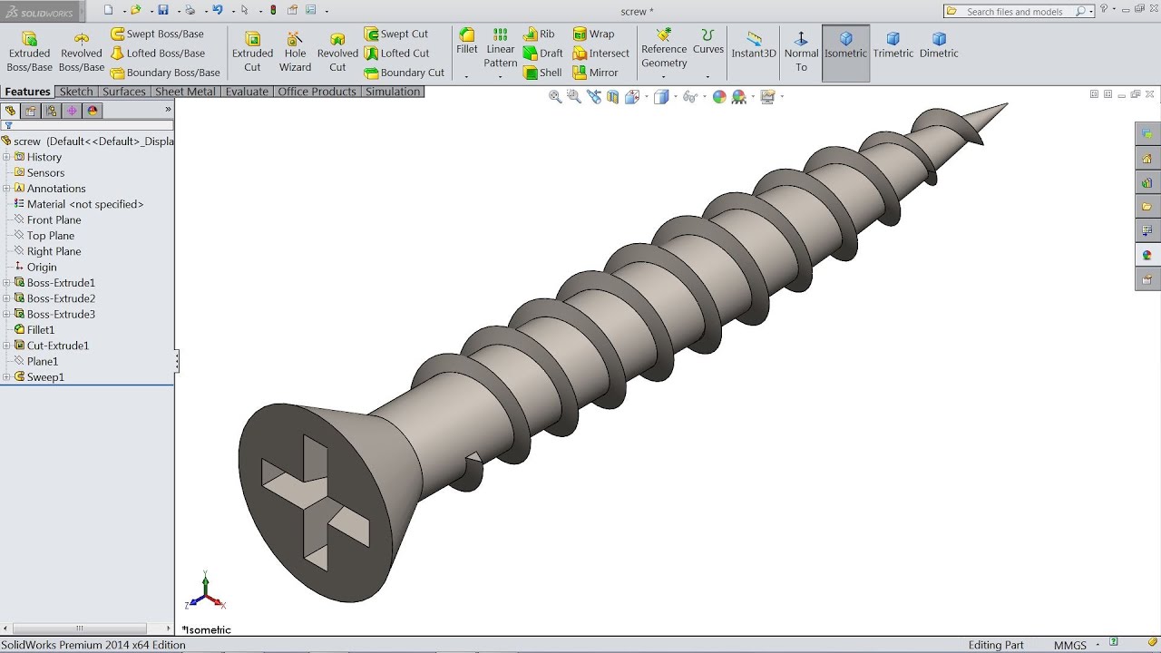
Almost there! Now we need to *carve* the thread into the cylinder, following the spiral path we just created. For this, we'll use the "Swept Cut" feature. First, you'll need a profile – the shape of the thread itself. A triangle is the most common, so sketch a small triangle on a plane perpendicular to the start of your helix. Make sure one point of the triangle touches the helix.
Now, activate the "Swept Cut" command. SolidWorks will ask you two things: "Profile" and "Path". For "Profile", select the triangle you just sketched. For "Path", select the helix. SolidWorks will then *magically* sweep that triangle along the helix, cutting the thread into your cylinder. Like a tiny, determined router carving its way through digital metal.
Click OK. Cross your fingers… and BAM! You have a screw thread. Isn't that satisfying? Now you can rotate it around in Solidworks and admire your work.
Finishing Touches: The Screw Head (No Screaming Required)
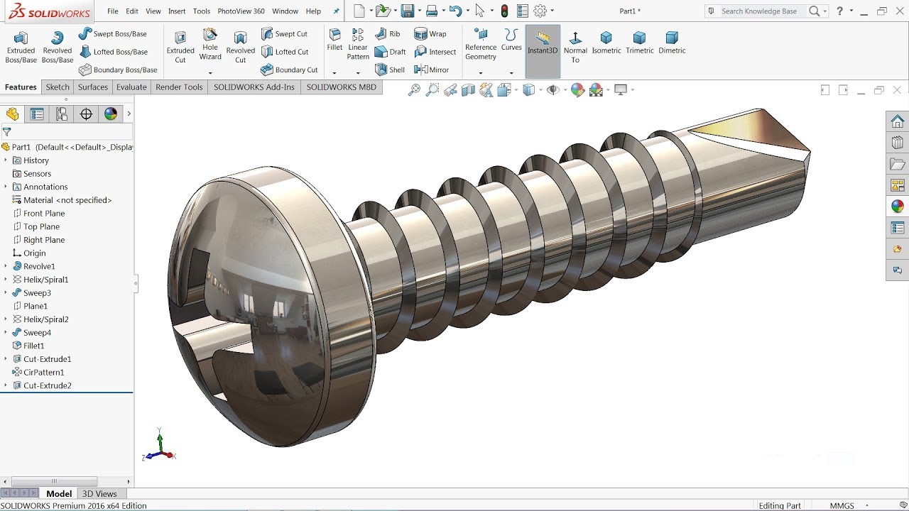
No screw is complete without a head! Go back to the top of your screw (the opposite end from the thread). Create another circle on the face of the cylinder. Extrude it. Make it bigger in diameter than the cylinder – maybe 10mm or so – and a few millimeters thick. Now you've got a basic screw head.
You can get fancy with the head shape using additional features like "Chamfer" or "Fillet" to round off the edges. You can even create a slot for a screwdriver using a rectangular cut. The possibilities are endless! Just remember to save your work. Name it something cool, like "Screw_of_Destiny.SLDPRT".
You Did It!
Congratulations! You've created a screw in SolidWorks. It might not be perfect (yet!), but you've mastered the basics. Now you can experiment with different sizes, thread pitches, and head shapes. You're on your way to becoming a virtual screw-making master. And the next time you're missing a screw from that IKEA flatpack, you can just… 3D print one! (Okay, maybe not yet, but a guy can dream, right?).