Ever wondered how all those tiny, but oh-so-important screws are designed? Or perhaps you're itching to create your own custom hardware for a cool project? Well, designing a screw in SolidWorks might sound intimidating, but trust me, it's surprisingly fun and incredibly useful! It's like digital Lego, but with a practical purpose.
Why is this useful, you ask? For beginners in CAD, designing a screw is a fantastic way to learn basic 3D modeling techniques like sketching, extruding, and using the helix tool. It's a mini-project that solidifies fundamental concepts. For families, especially those into DIY projects, imagine designing custom screws for a birdhouse or a model rocket! It brings a whole new level of personalization and engineering fun to family time. And for the hobbyists and makers out there, creating screws in SolidWorks opens up a world of possibilities. Need a specific thread size for a vintage camera repair? Want a unique screw head design for your steampunk gadget? You can design and potentially 3D print it all!
The beauty of SolidWorks is its flexibility. You're not limited to standard screw designs. You can create variations with different head types – flat, round, pan, even custom shapes like stars or gears. Experiment with different thread pitches for specific applications. Want a finer thread for greater holding power? No problem! You can even design screws with unique materials and finishes virtually, which is great for visualizing your final product.
So, how do you get started? Here’s a simplified breakdown:
- Start with a sketch: Draw a circle on a plane. This will be the diameter of your screw shaft.
- Extrude the shaft: Give your circle some height to create the main body of the screw. This determines the screw's length.
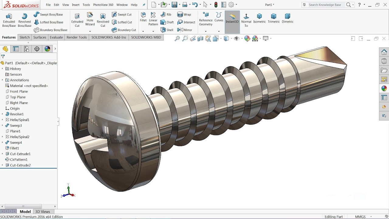
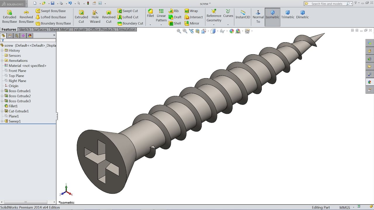
- Create the thread: This is where the "helix" tool comes in. Draw a circle on the end of the shaft (the same diameter as before). Then, use the helix and spiral feature to create a spiral path. This defines the thread pitch and height.
- Cut the thread: Now, sketch a triangle on a plane that intersects the helix path. This triangle represents the shape of the thread. Use the "swept cut" feature to cut along the helix path, creating the threads.
- Add the head: Sketch the shape of your desired screw head on the opposite end of the shaft. Extrude this sketch to create the head. You can chamfer or fillet the edges for a smoother look.
Simple Tips for Success:
- Don't be afraid to experiment! SolidWorks is all about trial and error.
- Use the help documentation. SolidWorks has extensive tutorials and explanations.
- Start with simple designs and gradually increase complexity.
- Watch online tutorials. There are tons of free resources available.
- Pay attention to your sketch constraints. Fully defined sketches are crucial for accurate models.
Designing screws in SolidWorks is more than just creating a digital object; it's about understanding fundamental engineering principles, unleashing your creativity, and solving real-world problems. So, dive in, experiment, and enjoy the process of building your own virtual hardware! You might be surprised at how much you learn and the cool things you can create.